Automatic Pocket Door and Motorized Sliding Track Systems
For all installation drawings and more information please see the Downloads Page.
Dado Automation does not provide installation services. The typical installation in handled by the General Contractor. All PDF files, including installation guides, are found on the DOWNLOADS page. For a basic overview of a standard pocket door application, please see the Framing Guide PDF.
Based on a Finished Opening and Width and Height, a PDF drawing can be generated to show the ACTUAL door panel size to fit the opening, including the dimensions from:
Finished Floor To bottom of door
Finished Floor to bottom of support header
Finished Floor to ceiling
Finished Floor to top of door panel
EXAMPLE WOOD DOOR DIMENSION DRAWING
EXAMPLE GLASS DOOR DIMENSION DRAWING
Typically, the install is done with the basic drawings found on the Downloads page.
Automatic Pocket Door and Motorized Sliding Track Systems.
Consultation via email and phone is available to insure a smooth install process. Custom shop drawings can be prepared on request(depending on the complexity and time required to prepare such drawings, a design fee may be required). No prior experience with the Dado System is required. The motor is shipped with wires ready to connect to the Master Controller. There are no special requirements for the Master Controller AC power.
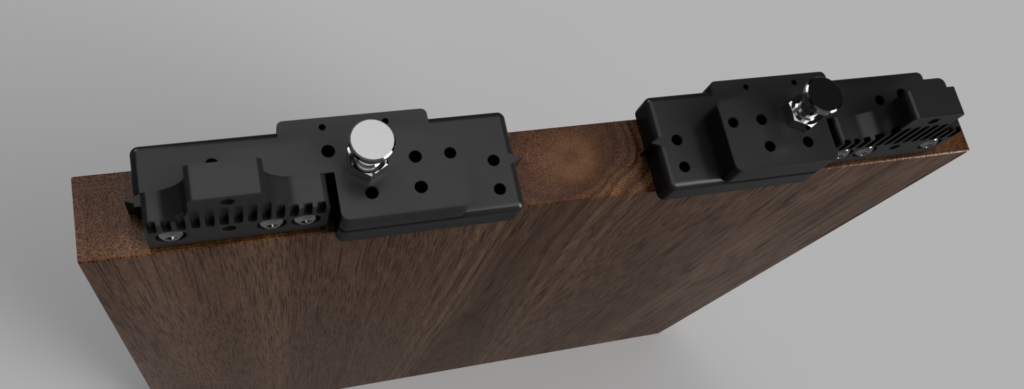
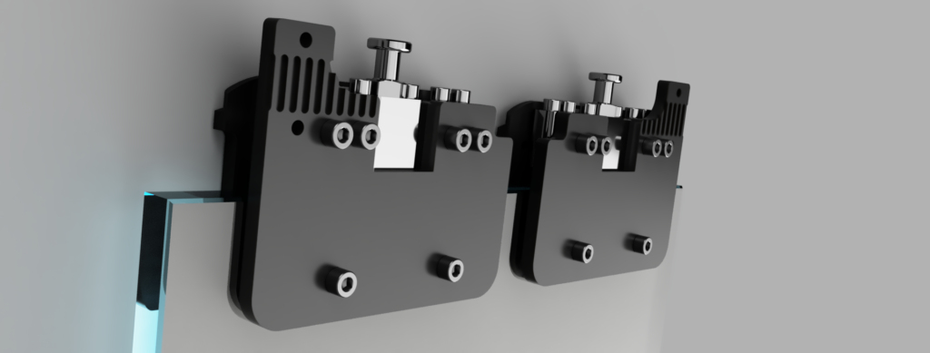
The minimum framing requirement to install the door is the support header. The track system attaches to the support header with threaded rod. The support header can be any thickness, as long as it has the structural integrity to support the load. Support materials range from steel angle or plate, a 4×4 or 4×6 is common. For a 2×4 stud wall a 4×6 turned on edge is recommended. The main criteria is that the threaded rod needs access above and below the support header to adjust the nuts on the threaded rod. There are alternatives if there is no access above the header.